
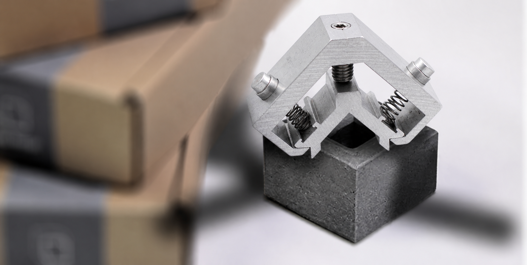
Angle Brackets
Product ID: 7469
Angle brackets with machined contact faces and fixing interfaces for connecting members at the angle required by the project drawing.
Product Description
The two legs provide mounting surfaces on separate planes and transfer forces between the connected members. Leg length, angle and hole position establish the installation geometry. Bracket thickness and the distance between fasteners and the loaded region influence bending and local bearing pressure. In curtain-wall connections, the complete joint must also accommodate the project movement, material compatibility and environmental exposure requirements. Application examples, subject to assembly design: a right-angle connection in a curtain-wall support or a custom angle mount between structural members. A hole or slot may be intended for installation adjustment, service movement or both, and the connection detail must identify which. Unintended tightening across a required sliding interface can restrain movement, while an unconstrained load-bearing interface can permit unwanted displacement.
Product Features
Two mounting legs establish the required connection angle. Machined faces provide defined contact regions. Fixing holes or slots match the project connection. Leg geometry and hole edge distances coordinated with the load path. Engineering focus: installation adjustment and service movement separated in the joint detail.
Technical Specifications
Indicative custom specification for RFQ; final drawing and quotation govern. Materials: 304 / 316L stainless plate; carbon-steel plate with a specified protective coating as an alternative. Tolerances: Proposed leg dimensions +/-0.20 mm, included angle +/-1 degree and fixing-hole position 0.10 mm; selected machined faces separately controlled. Surface treatment / roughness: Stainless brushing/passivation; carbon-steel hot-dip galvanizing to a selected ISO 1461 coating class. Holes/clearances allow for coating. Indicative size range: Leg lengths 20-150 mm each; width 20-100 mm; thickness 2-8 mm; hole/slot geometry follows the connection design. Proposed process: Plate cutting / punching/drilling / bending or machining as drawn / deburring / selected coating / angle/hole checks. MOQ: Reference lot 100 pcs per part number; final MOQ per quotation. Target lead time: Target 2-3 weeks (10-15 working days) after drawing/material/order approval; final quotation governs. Reference standards: ASTM A240/A240M; ISO 1101:2017; ASTM A967/A967M; ISO 1461:2022; apply only to the selected material/process and scope. Note: Fixed versus sliding connection details and approved structural loads govern selection; coating compliance does not certify the whole joint. Size-range limits are not all combinable. Surface/heat treatments are project-managed through qualified partners where required.
Related products
More from Curtain Wall Components
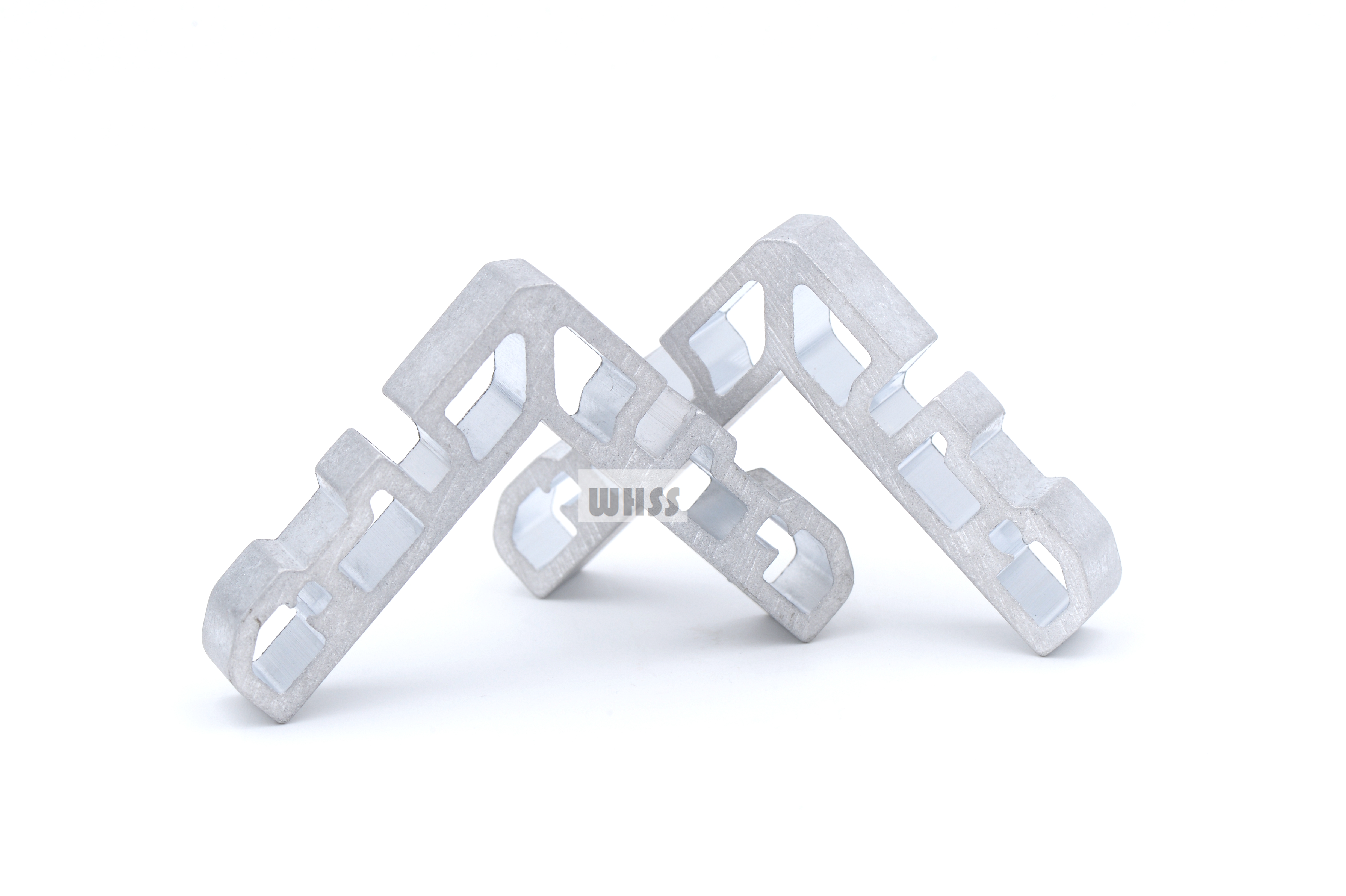
Structural Connection Components
Custom structural connection components with shaped sections, open cut-outs and fixing interfaces for project-defined assemblies.
View Details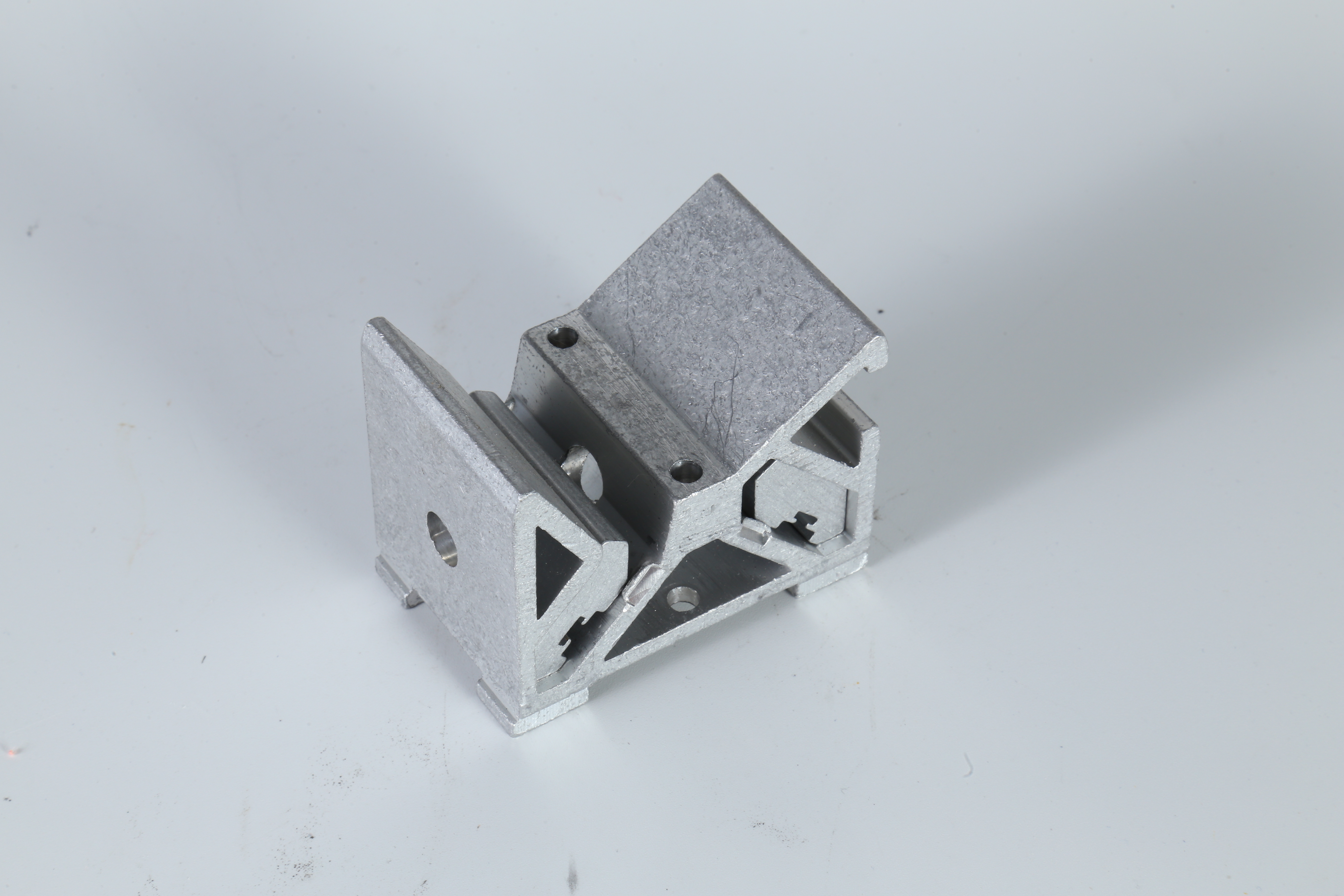
Machined Support Brackets
Machined support brackets with angled sections, reference faces and fixing interfaces for custom equipment or structural connections.
View Details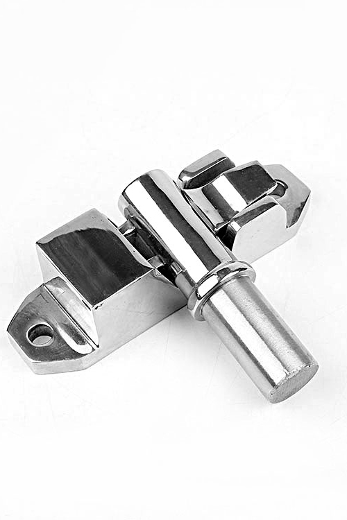
Hardware Fasteners
Custom fastening and connection parts with machined cylindrical, mounting or threaded interfaces for project-specific joints.
View Details