
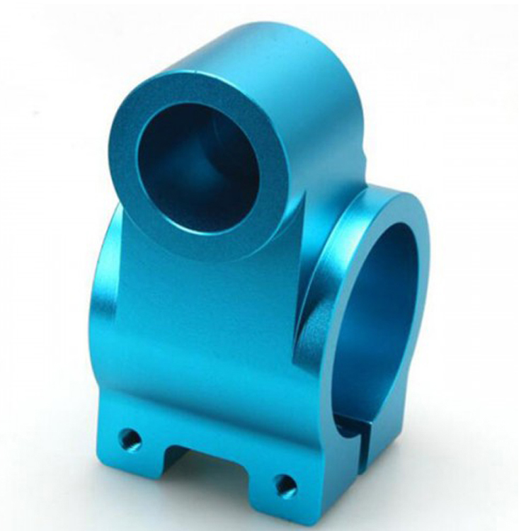
Machined Clamping Brackets
Product ID: 7467
Split clamping brackets with circular bores and fastening holes for customer-designed shaft, tube or cylindrical-component mounting.
Product Description
The split opening allows a drawing-defined clamping section to deform under screw preload and grip a mating cylindrical component. Bore geometry controls contact and location, while the bracket body connects the clamped part to its mounting structure. The required clearance, split width and wall section depend on the mating diameter and allowable deformation. Holding force is determined by the complete clamp design, friction and tightening conditions. Application examples, subject to assembly design: mounting a cylindrical sensor, retaining a guide tube or attaching a shaft-mounted component. The split should retain the clearance required by the design at the intended preload; premature closure can limit useful clamping deformation. The effective grip also depends on bore contact length, mating-surface condition and the permissible pressure on the clamped component.
Product Features
Circular bores provide cylindrical locating interfaces. Split section enables screw-actuated clamping where specified. Fastening holes establish preload and mounting connections. Bore alignment and contact geometry matched to the mating part. Engineering focus: remaining split gap and bore contact under the specified clamp load.
Technical Specifications
Indicative custom specification for RFQ; final drawing and quotation govern. Materials: 6061-T6 / 7075-T6 aluminium; 304 stainless option with a separate clamp-stiffness review. Tolerances: Proposed locating bore H7 only where selected by the mating design; bore spacing +/-0.03 mm; split width +/-0.05 mm. General metal sizes ISO 2768-1-m. Surface treatment / roughness: Aluminium: clear/coloured anodizing 10-15 um; stainless: passivation. Bore contact Ra max. 1.6 um before finish; fit controlled after treatment. Indicative size range: Body length 30-160 mm; width 20-100 mm; clamp bores 8-60 mm; split 1-4 mm as designed. Proposed process: CNC milling / boring/reaming / slotting / drilling/tapping / deburring / finish / clamp-fit verification. MOQ: Reference lot 50 pcs per part number; final MOQ per quotation. Target lead time: Target 2-3 weeks (10-15 working days) after drawing/material/order approval; final quotation governs. Reference standards: ASTM B209/B209M; ASTM A276/A276M; ISO 286-2:2010; ISO 1101:2017; ISO 7599:2018; ASTM A967/A967M; apply only to the selected material/process and scope. Note: H7 is a candidate locating tolerance, not an automatic bearing/clamp fit; verify holding force and remaining split gap. Size-range limits are not all combinable. Surface/heat treatments are project-managed through qualified partners where required.
Related products
More from New Energy Vehicle Parts
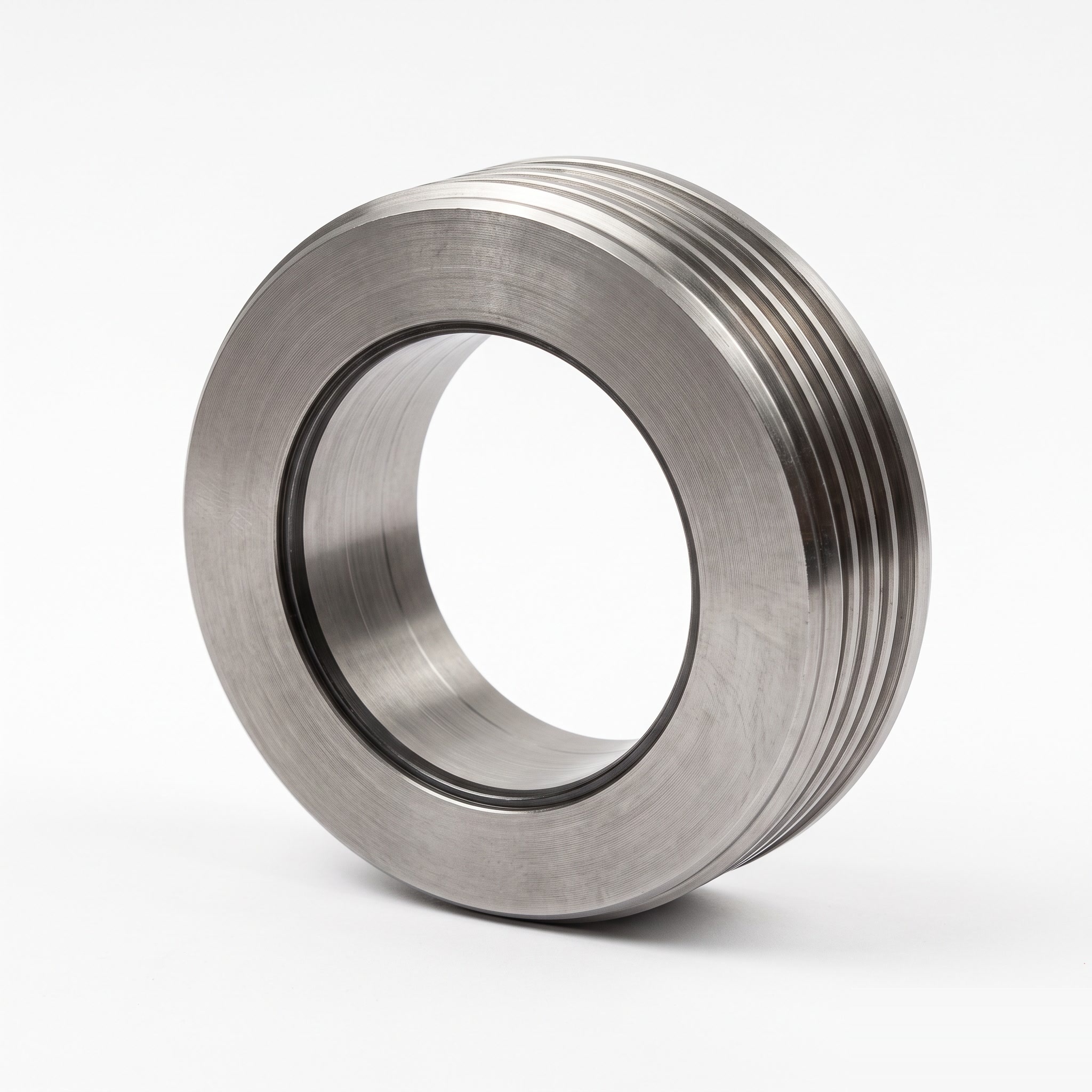
Wheel Inner Rings
Custom machined wheel inner rings with a central bore, stepped faces and circumferential grooves for drawing-defined locating and mating interfaces.
View Details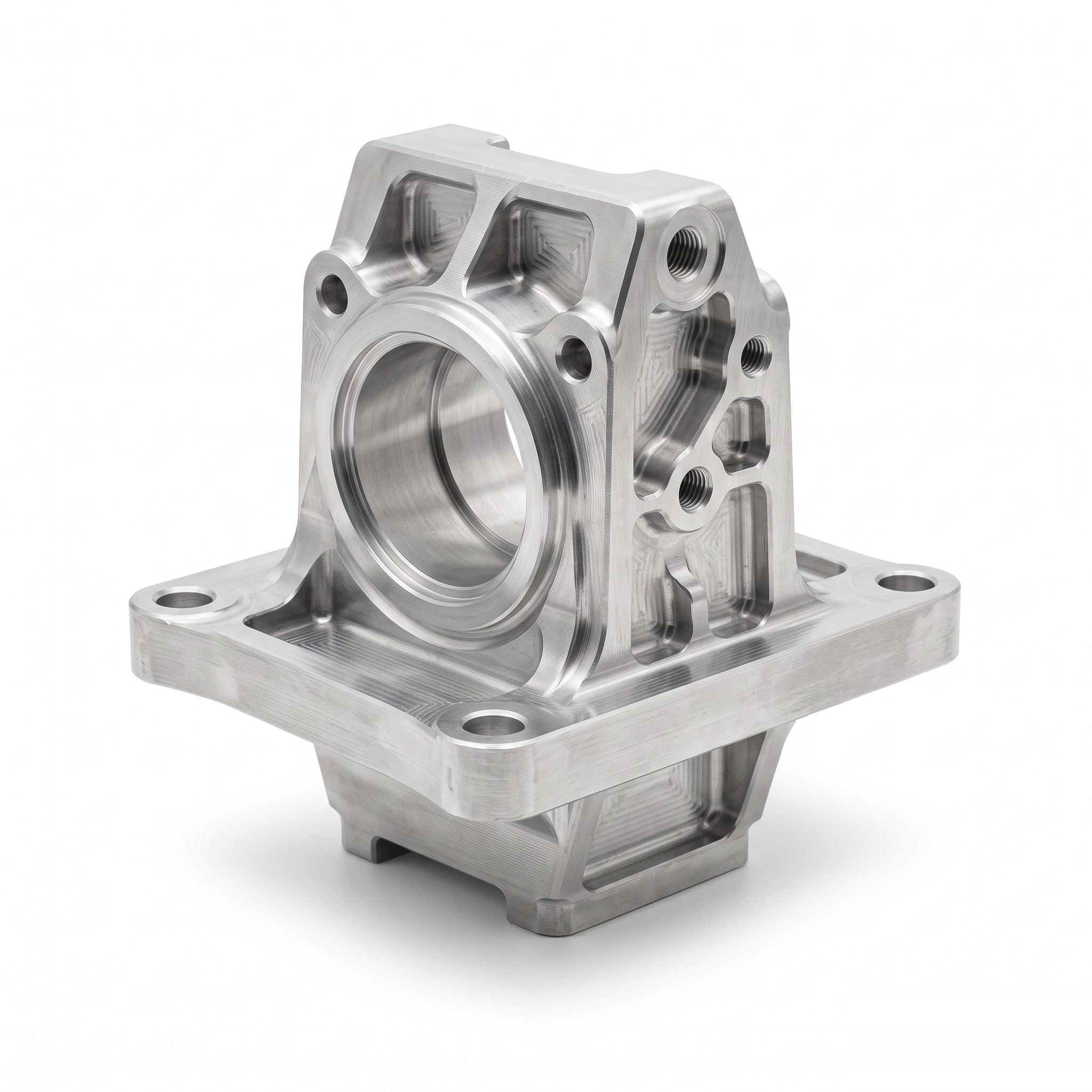
Steering Bases
Custom steering base housings with a large circular bore, reinforcing ribs and a mounting flange for the interfaces specified by the steering assembly design.
View Details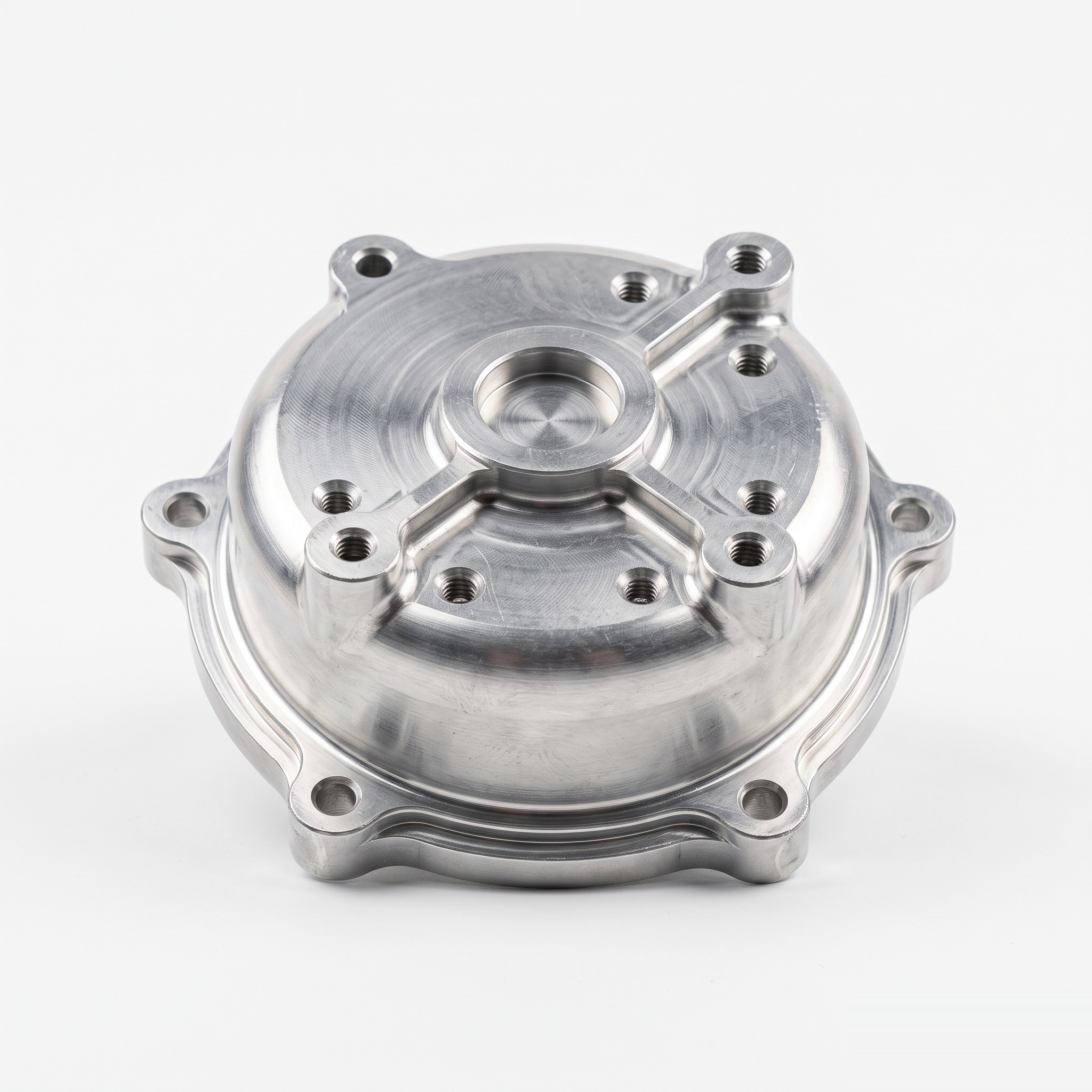
Steering Covers
Steering assembly covers with a raised central section, circular mounting flange and fixing holes, customized to the required internal clearance and housing interface.
View Details