
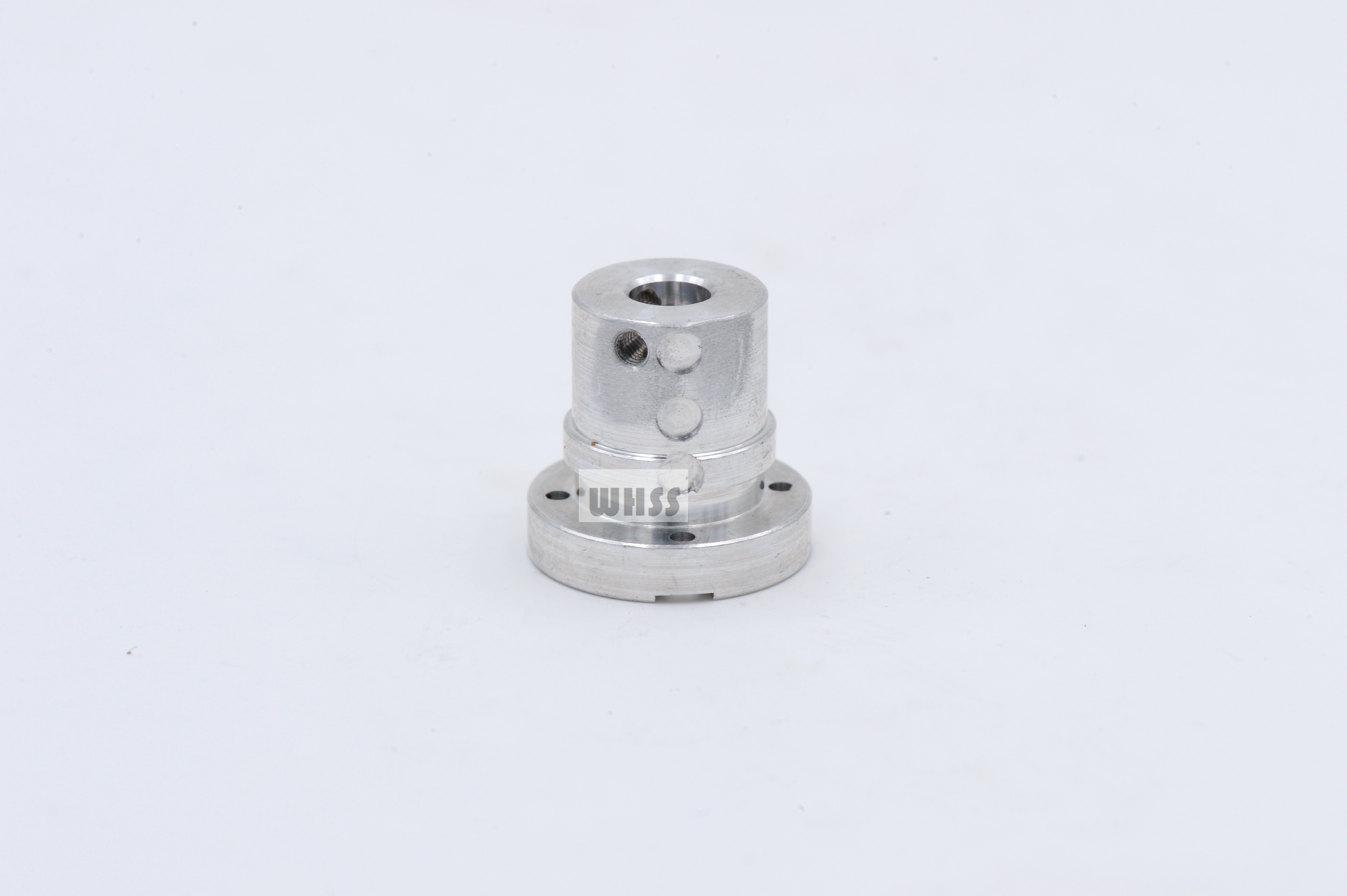
Flanged Mechanism Components
Product ID: 7863
Flanged cylindrical mechanism components with radial holes and mounting features for custom mechanical operating assemblies.
Product Description
The cylindrical portion provides a mating or locating interface, and the flange provides a mounting face or axial stop. Radial holes may accommodate pins, screws or access features as defined by the mechanism drawing. Their angular position and relationship to the main axis establish the orientation of adjoining parts. Torque or axial-force transfer must follow the actual pin, fastener, fit or contact arrangement. Application examples, subject to assembly design: a flanged shaft connector or an operating-element interface in a mechanical linkage. A cross pin transfers load through pin contact and shear, while a grub screw or clamping interface uses a different contact mechanism. The radial hole should therefore be dimensioned for its intended fastener and assembly method, including edge distance and access, rather than treated as a generic opening.
Product Features
Cylindrical interface establishes the specified radial fit. Flange provides an axial reference or mounting face. Radial holes match the mechanism orientation. Main-axis and hole-position relationships defined for assembly. Engineering focus: radial-hole orientation and the specified shaft-retention mechanism.
Technical Specifications
Indicative custom specification for RFQ; final drawing and quotation govern. Materials: 1045 / 4140 steel, 304 stainless or 6061-T6 aluminium, selected for the shaft-connection loads and environment. Tolerances: Proposed locating bore H7 if selected, flange-face runout 0.03 mm and radial-hole position 0.05 mm to defined datums; threads separately specified. Surface treatment / roughness: Steel black oxide + preservative, stainless passivation or aluminium anodizing 10-15 um; marked mating faces Ra max. 1.6 um before finish. Indicative size range: Flange OD 20-100 mm; body OD 10-60 mm; length 15-100 mm; radial holes 2-10 mm as drawn. Proposed process: Turning/boring/facing / radial drilling/tapping / milling if required / deburring / selected finish / fit/orientation checks. MOQ: Reference lot 100 pcs per part number; final MOQ per quotation. Target lead time: Target 2-3 weeks (10-15 working days) after drawing/material/order approval; final quotation governs. Reference standards: ASTM A29/A29M; ASTM A276/A276M; ASTM B221/B221M; ISO 286-2:2010; ISO 1101:2017; ISO 965-1:2026; ISO 21920-1:2021; ISO 11408:1999; ASTM A967/A967M; ISO 7599:2018; apply only to the selected material/process and scope. Note: Pin, grub-screw and friction-clamp connections use different retention mechanisms; the final torque/load is design-specific. Size-range limits are not all combinable. Surface/heat treatments are project-managed through qualified partners where required.
Related products
More from Valve Operating Components
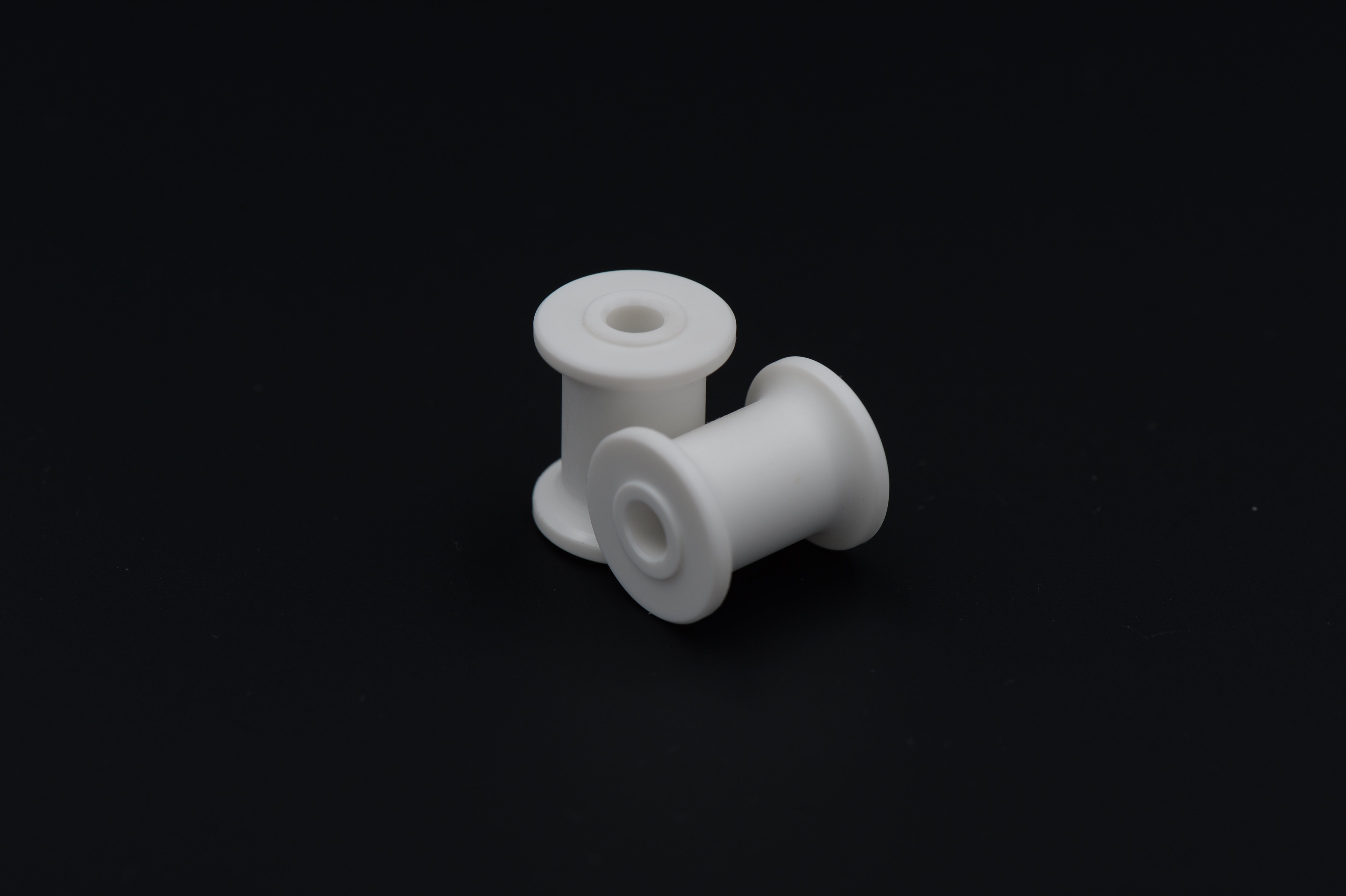
Spool-Shaped Guide Components
Spool-shaped guide components with a central bore and flanged ends for customer-defined guidance, spacing or retention arrangements.
View Details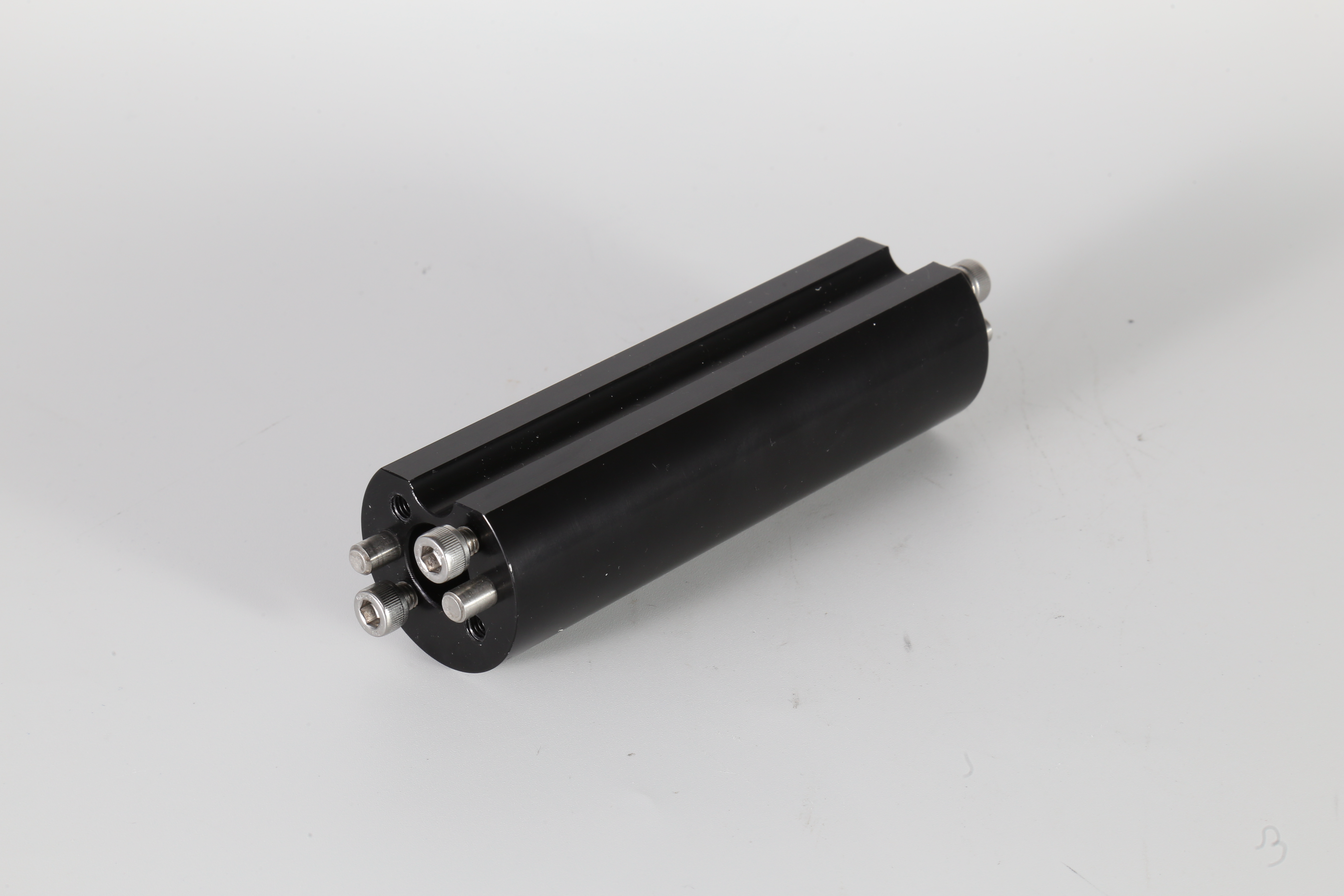
Mechanical Roller Assemblies
Mechanical roller assemblies with mounting and guide features for customer-designed motion, contact or operating mechanisms.
View Details