
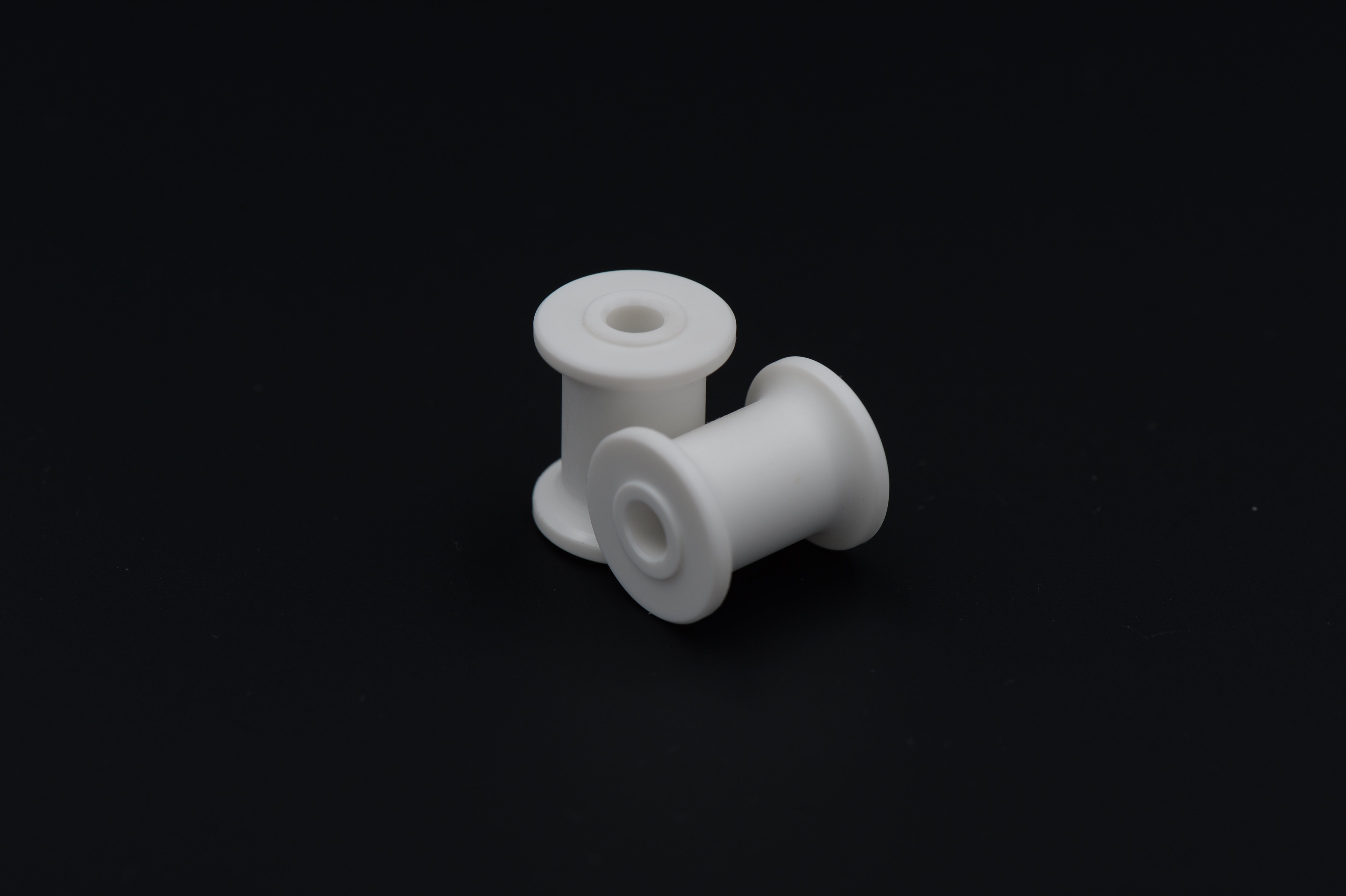
Spool-Shaped Guide Components
Product ID: 7864
Spool-shaped guide components with a central bore and flanged ends for customer-defined guidance, spacing or retention arrangements.
Product Description
The central bore establishes the shaft or fastener interface, while the flanged ends define lateral boundaries around the center section. Depending on the assembly, the component may guide an adjoining member, set spacing or retain a defined contact path. Fixed and rotating versions require different fits and contact conditions. Flange spacing, bore alignment and transition radii should be coordinated with the mating geometry. Application examples, subject to assembly design: a guide spool, a flanged spacer or a sliding guide sleeve when specified by the assembly. Where the component serves as a plain sliding guide, contact pressure and sliding speed jointly influence frictional heating. For a fixed spacer, the relevant requirements instead center on seating and compression. The same outside shape can therefore require different bore fits, finishes and materials.
Product Features
Central bore provides the specified mounting interface. Flanged ends establish lateral retaining surfaces. Center section matched to the contact or spacing function. Transition radii and clearances coordinated with adjoining parts. Engineering focus: flange clearances and contact duty defined before selecting the material.
Technical Specifications
Indicative custom specification for RFQ; final drawing and quotation govern. Materials: POM-C / PA66 for a reviewed polymer guide; 304 stainless or 6061-T6 aluminium for separate metal spacer/guide routes. Tolerances: Proposed polymer sizes +/-0.10 mm; metal locating bores H7 only if selected; flange spacing +/-0.05 mm; running clearance separately defined. Surface treatment / roughness: Polymer as-machined/deburred, contact faces Ra max. 3.2 um where appropriate; metal guide faces Ra max. 1.6 um before passivation or anodizing 10-15 um. Indicative size range: Flange OD 15-80 mm; bore 4-30 mm; length 10-80 mm; flange spacing 5-50 mm subject to contact layout. Proposed process: Stock cutting / turning/boring / flange/profile finishing / deburring / route-specific finish / clearance/contact checks. MOQ: Reference lot 100 pcs per part number; final MOQ per quotation. Target lead time: Target 2-3 weeks (10-15 working days) after drawing/material/order approval; final quotation governs. Reference standards: ASTM D6778; ASTM D5989; ASTM A276/A276M; ASTM B221/B221M; ISO 286-2:2010; ISO 1101:2017; ISO 21920-1:2021; ASTM A967/A967M; ISO 7599:2018; apply only to the selected material/process and scope. Note: Sliding, rolling and fixed-spacer functions require different fits/materials; do not infer bearing capacity from the spool shape. Size-range limits are not all combinable. Surface/heat treatments are project-managed through qualified partners where required.
Related products
More from Valve Operating Components
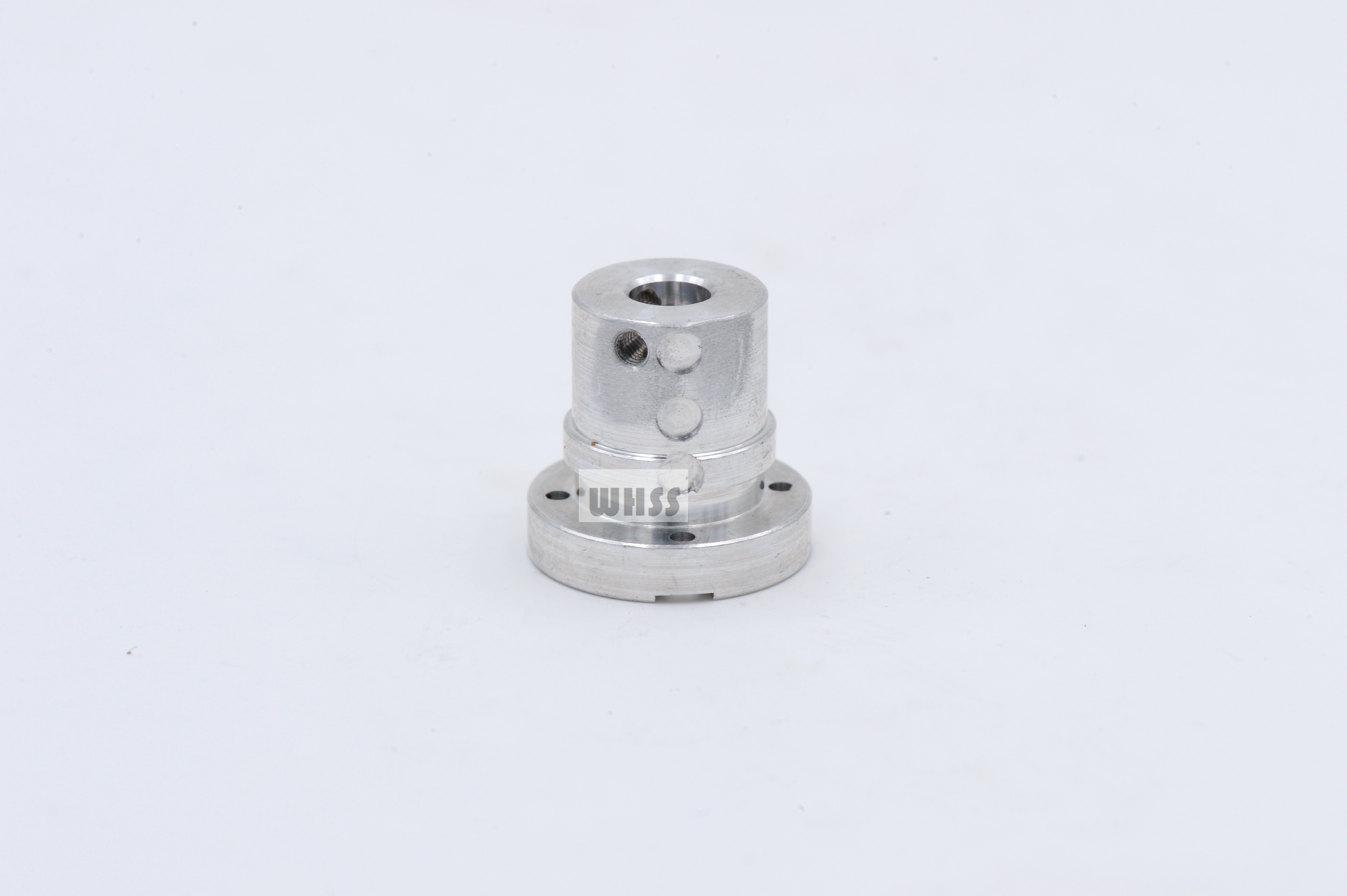
Flanged Mechanism Components
Flanged cylindrical mechanism components with radial holes and mounting features for custom mechanical operating assemblies.
View Details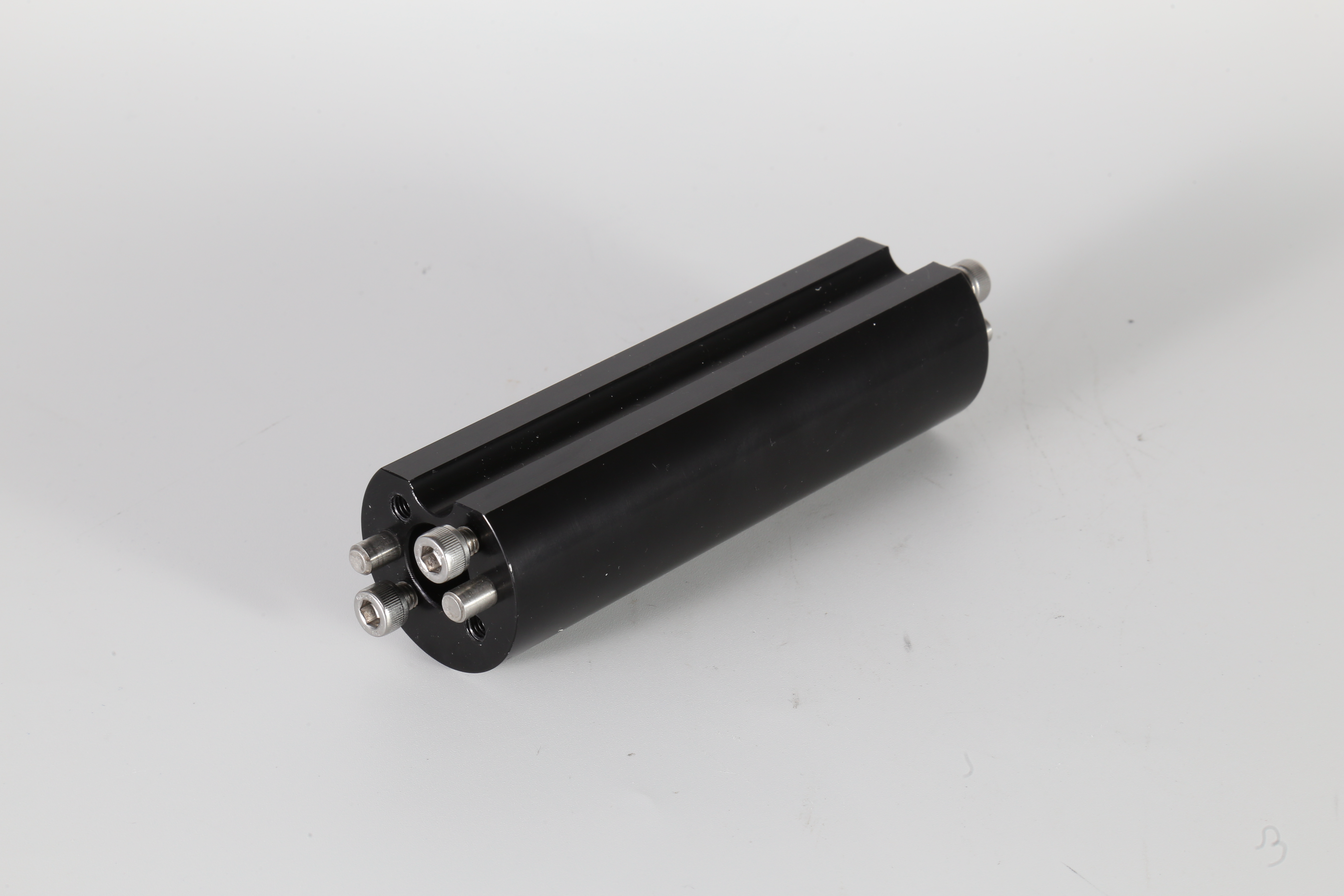
Mechanical Roller Assemblies
Mechanical roller assemblies with mounting and guide features for customer-designed motion, contact or operating mechanisms.
View Details