
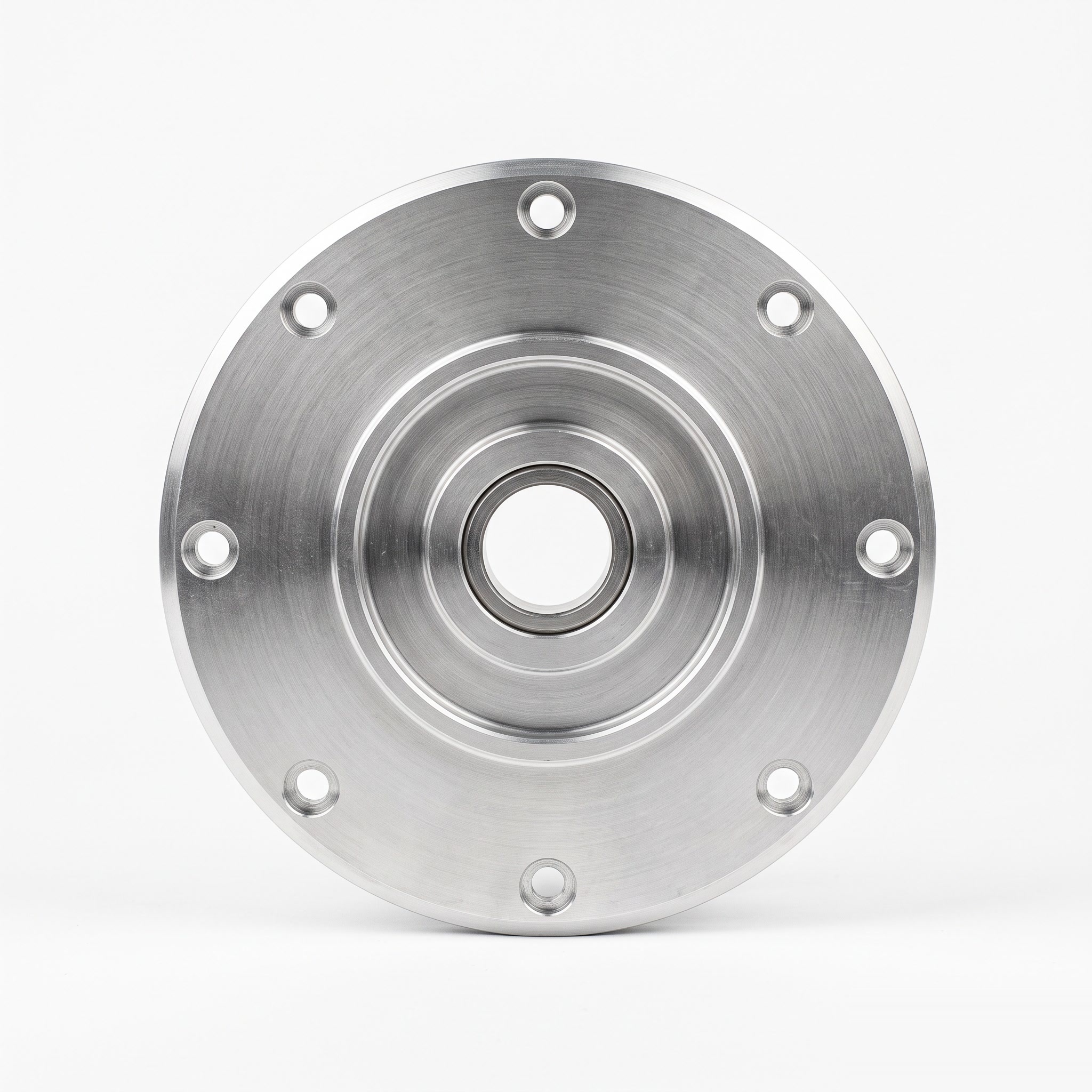
Motor Cover Plates
Product ID: 10509
Circular motor cover plates with a central bore, stepped faces and perimeter fixing holes for drawing-defined motor housing interfaces.
Product Description
The cover plate closes the motor-end interface and establishes the position of the features specified around the shaft opening. Concentric steps can locate the plate against the mating housing. Where the design includes a bearing or seal seat, the bore finish and face relationship are coordinated with that component. Bolt-hole position and contact-face flatness affect seating and assembly alignment. Application examples, subject to assembly design: a motor end closure or a bearing-support end plate when included in the customer design. For a bearing-support version, the housing fit must reflect which bearing ring sees rotating load and whether axial movement is required. A uniformly tight fit at every interface can interfere with the intended thermal-expansion arrangement.
Product Features
Central opening matched to the shaft-area layout. Concentric steps provide housing-location interfaces. Perimeter fixing holes support a detachable end connection. Bearing or seal seats included only where specified on the drawing. Engineering focus: bearing-seat fit selected for ring loading and thermal conditions where a seat is specified.
Technical Specifications
Indicative custom specification for RFQ; final drawing and quotation govern. Materials: 6061-T6 aluminium bar/plate; 304 stainless alternative if required by the motor design. Tolerances: General metal sizes ISO 2768-1-m; proposed pilot +/-0.02 mm, face runout 0.03 mm and fixing-hole position 0.05 mm. Bearing seats use selected bearing fits. Surface treatment / roughness: Clear anodizing 10-15 um on aluminium or stainless passivation; marked pilot/seat faces Ra max. 1.6 um before finish. Indicative size range: OD 40-200 mm; thickness 5-35 mm; central opening 8-80 mm; pilot steps defined on the drawing. Proposed process: Turning/boring / step/face finishing / drilling/tapping / deburring / finish / pilot and face-runout checks. MOQ: Reference lot 50 pcs per part number; final MOQ per quotation. Target lead time: Target 2-3 weeks (10-15 working days) after drawing/material/order approval; final quotation governs. Reference standards: ASTM B221/B221M; ASTM B209/B209M; ASTM A276/A276M; ISO 1101:2017; ISO 286-2:2010; ISO 21920-1:2021; ISO 7599:2018; ASTM A967/A967M; apply only to the selected material/process and scope. Note: Bearing-seat fit and non-locating axial freedom are not established by the general pilot-tolerance example. Size-range limits are not all combinable. Surface/heat treatments are project-managed through qualified partners where required.
Related products
More from Industrial Automation Components
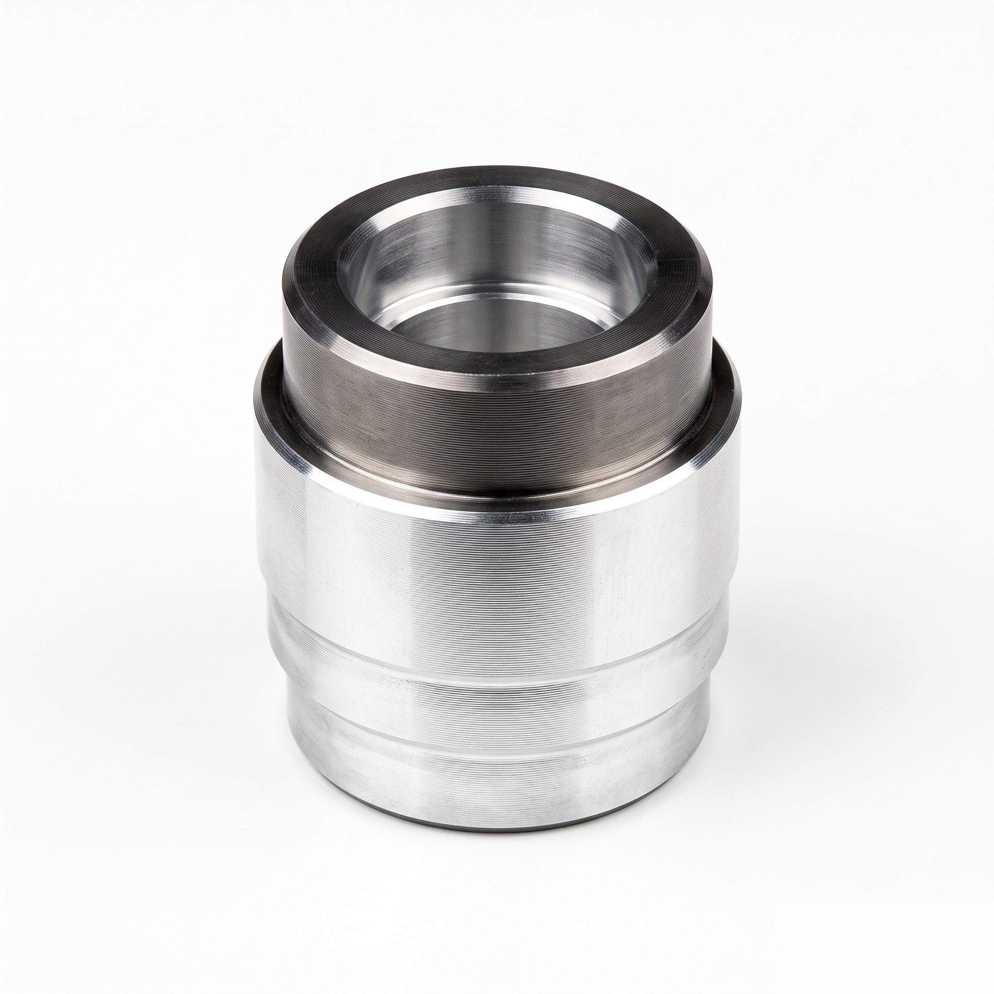
Actuator Test Sleeves
Stepped actuator test sleeves with a central bore and annular locating shoulders for customer-designed test fixtures.
View Details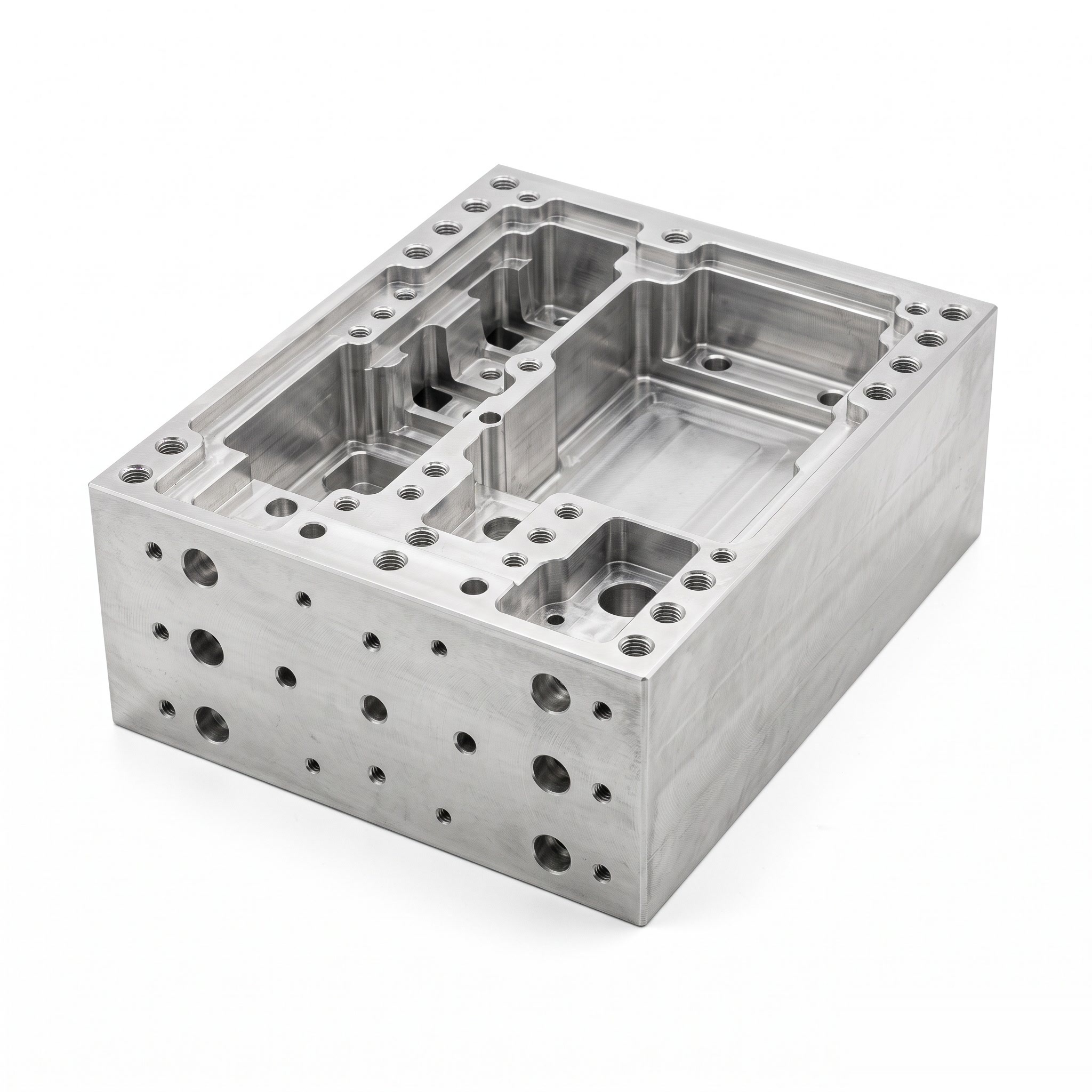
Machine Frame Housings
Custom machine frame housings with internal pockets, partition walls and mounting interfaces for integrated equipment layouts.
View Details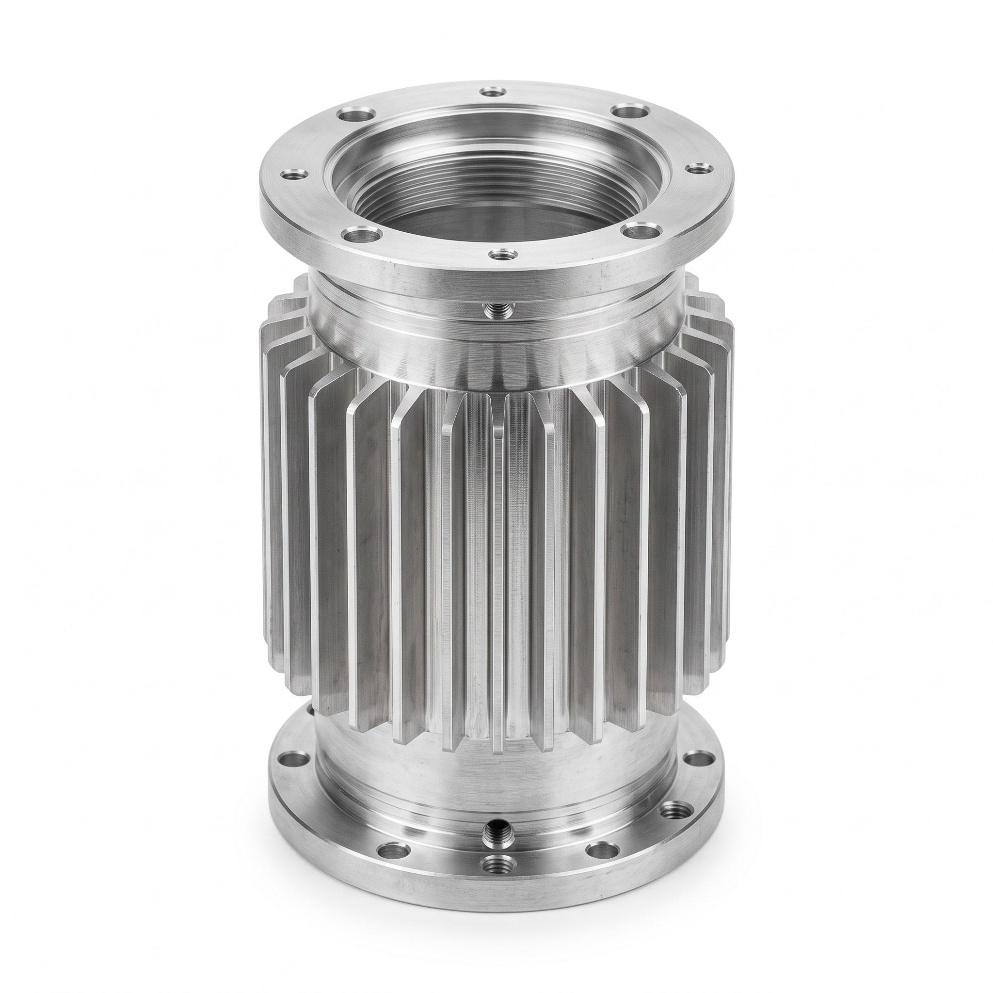
Motor Housings
Finned cylindrical motor housings with end flanges and mounting holes for customer-designed motor assemblies.
View Details