
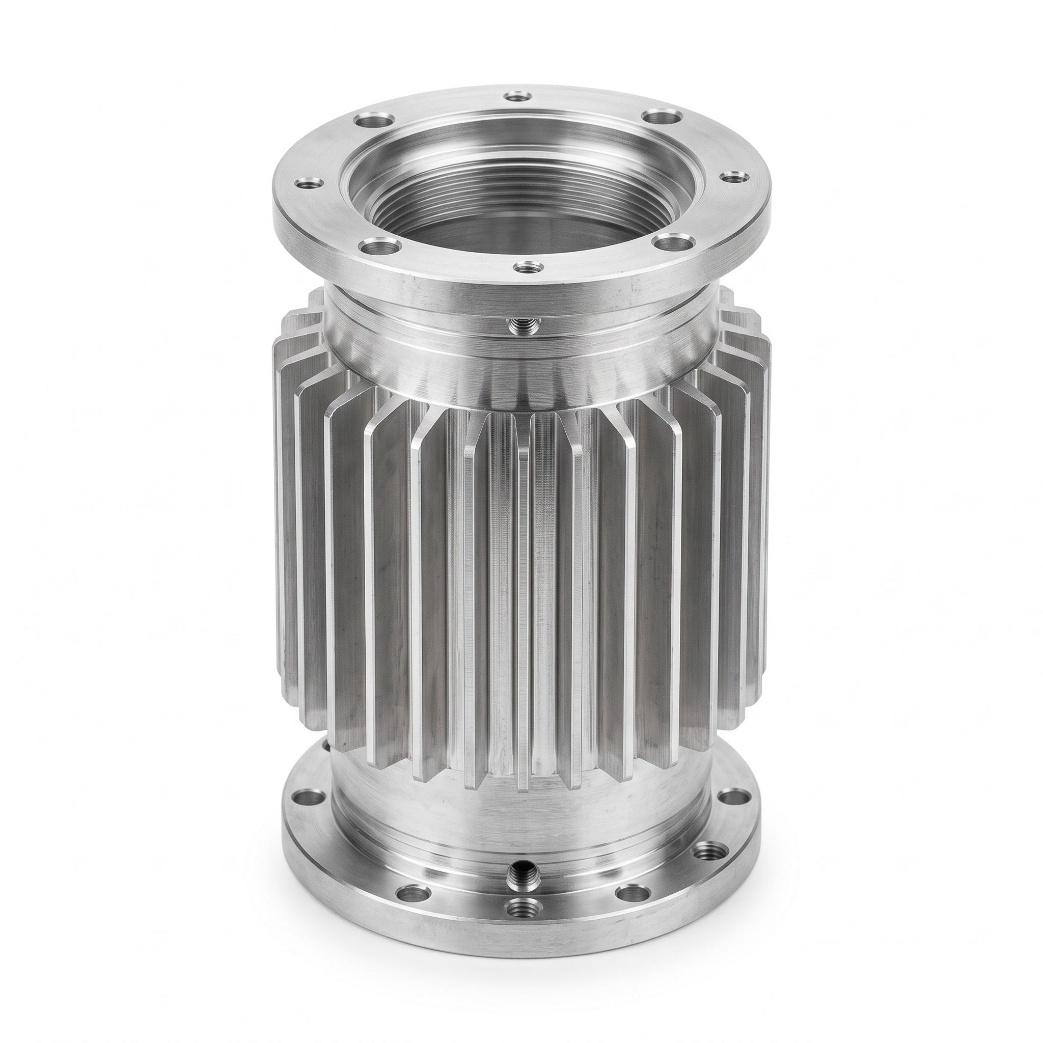
Motor Housings
Product ID: 10508
Finned cylindrical motor housings with end flanges and mounting holes for customer-designed motor assemblies.
Product Description
The cylindrical body accommodates the internal motor package and connects the end interfaces. External fins increase the area available for heat exchange with the surrounding air; actual cooling depends on material, airflow, heat paths and operating conditions. The main bore, flange faces and mounting pattern establish the mechanical alignment of the assembly. Fits must account for the specified installation method and operating temperature. Application examples, subject to assembly design: a finned frame for a custom motor or an electric-drive module with a cylindrical internal package. Closely spaced fins are useful only if the intended airflow can reach their surfaces. Heat also has to travel from the internal package to the housing, so interface contact and fit are relevant alongside the visible fin area. Cooling clearance around the installed housing should be specified.
Product Features
Cylindrical installation space for the specified motor package. External fins provide additional heat-transfer surface area. End flanges and mounting holes define assembly interfaces. Bore and flange relationships coordinated for alignment. Engineering focus: fin airflow, internal fit and mounting alignment treated as one housing design.
Technical Specifications
Indicative custom specification for RFQ; final drawing and quotation govern. Materials: 6063-T6 extruded aluminium for profile-based fins; 6061-T6 billet for a separately reviewed machined-fin route. Tolerances: Proposed finished bore +/-0.02 mm, end-face runout 0.03 mm and flange-hole position 0.05 mm; general machined sizes ISO 2768-1-m. Surface treatment / roughness: Clear/black anodizing 10-15 um option; fitted/contact zones masked or compensated. Marked bore/seat faces Ra max. 1.6 um before finish. Indicative size range: Body OD 50-200 mm; bore 30-160 mm; length 50-300 mm; fin height 3-15 mm with section/airflow review. Proposed process: Profile/billet sourcing / cut to length / CNC boring/end finishing / hole/thread machining / deburring / finish / inspection. MOQ: Reference lot 50 pcs per part number; final MOQ per quotation. Target lead time: Target 2-3 weeks (10-15 working days) after drawing/material/order approval; final quotation governs. Reference standards: ASTM B221/B221M; ISO 1101:2017; ISO 286-2:2010; ISO 21920-1:2021; ISO 7599:2018; apply only to the selected material/process and scope. Note: Extrusion tooling and initial samples have separate schedules. No cooling capacity or motor power rating is implied. Size-range limits are not all combinable. Surface/heat treatments are project-managed through qualified partners where required.
Related products
More from Industrial Automation Components
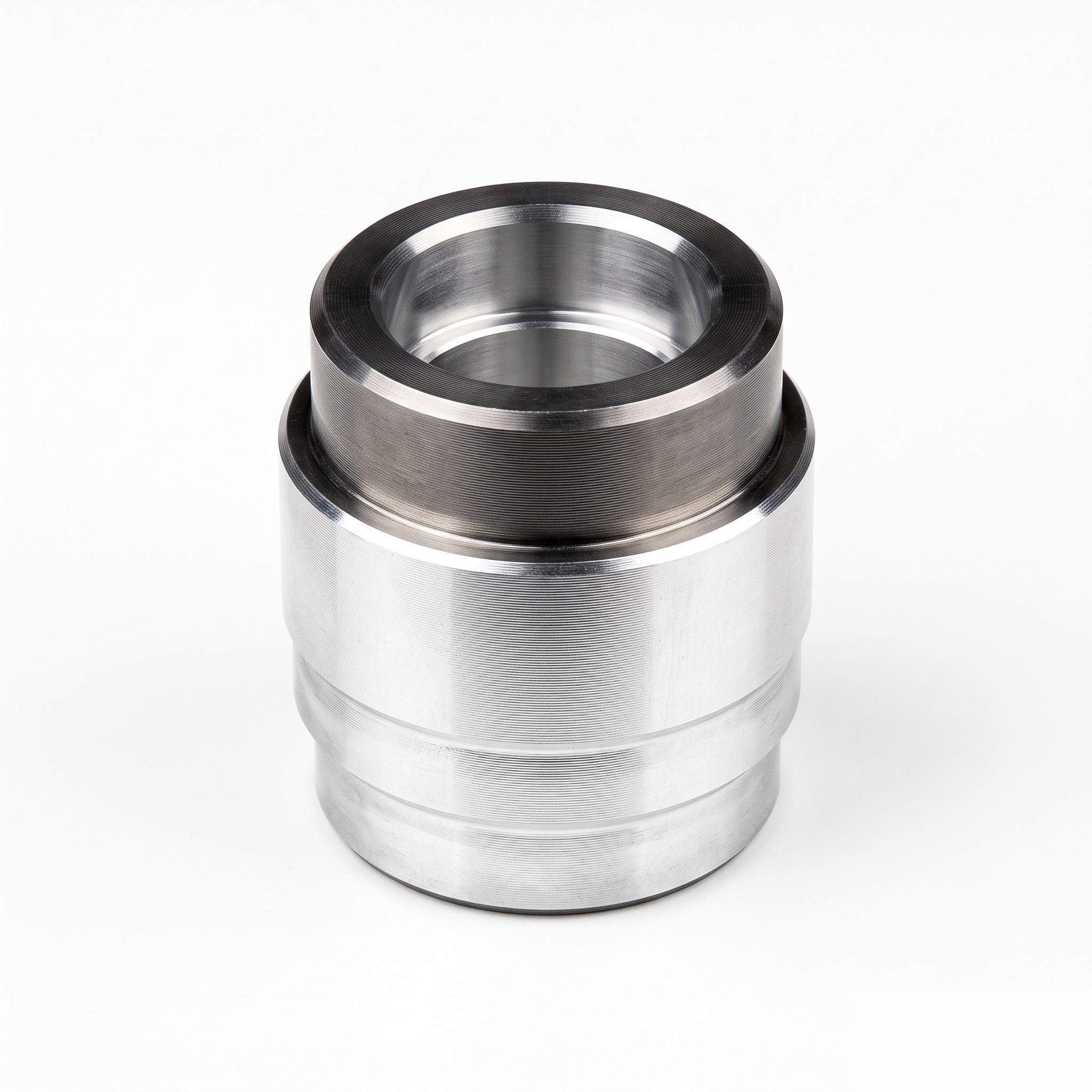
Actuator Test Sleeves
Stepped actuator test sleeves with a central bore and annular locating shoulders for customer-designed test fixtures.
View Details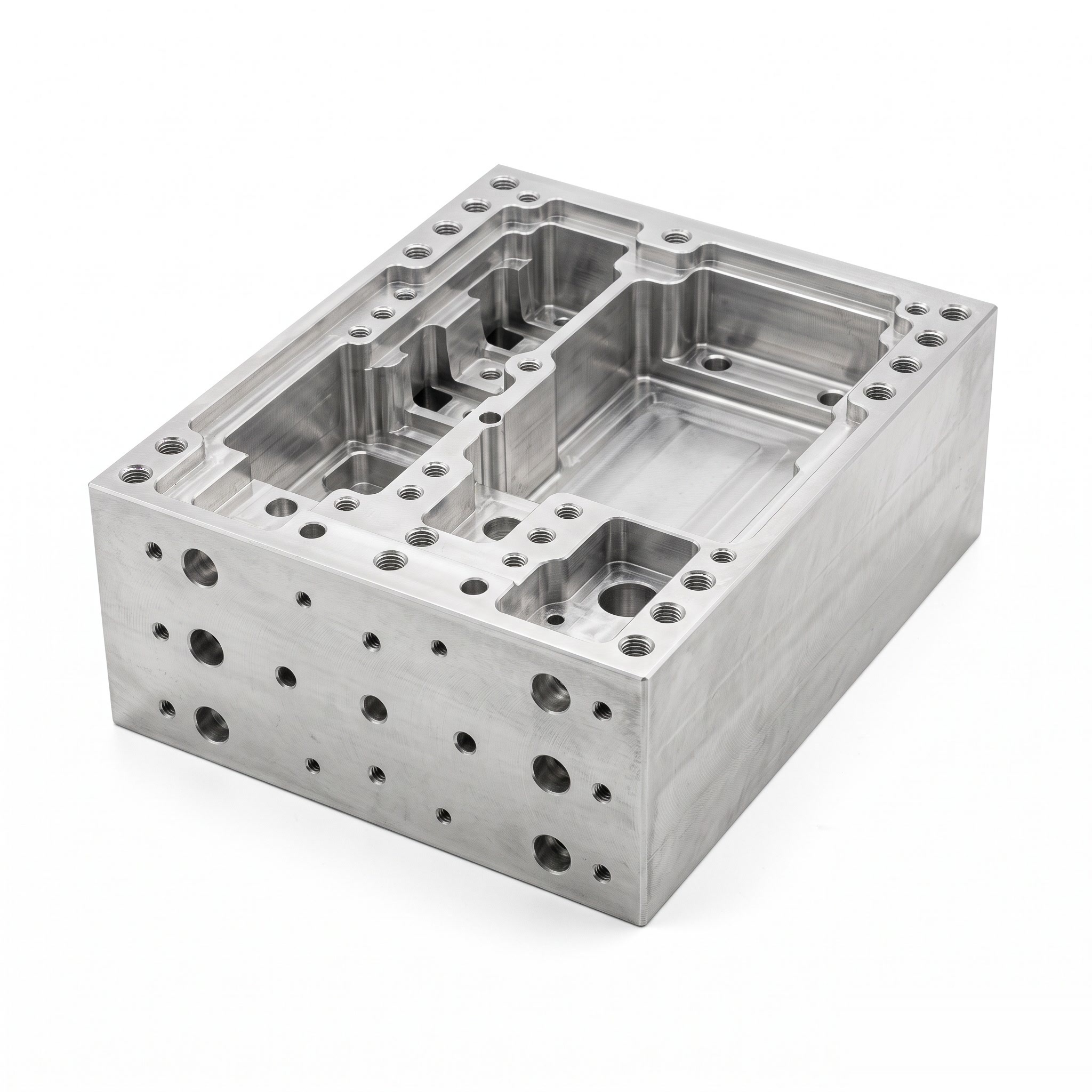
Machine Frame Housings
Custom machine frame housings with internal pockets, partition walls and mounting interfaces for integrated equipment layouts.
View Details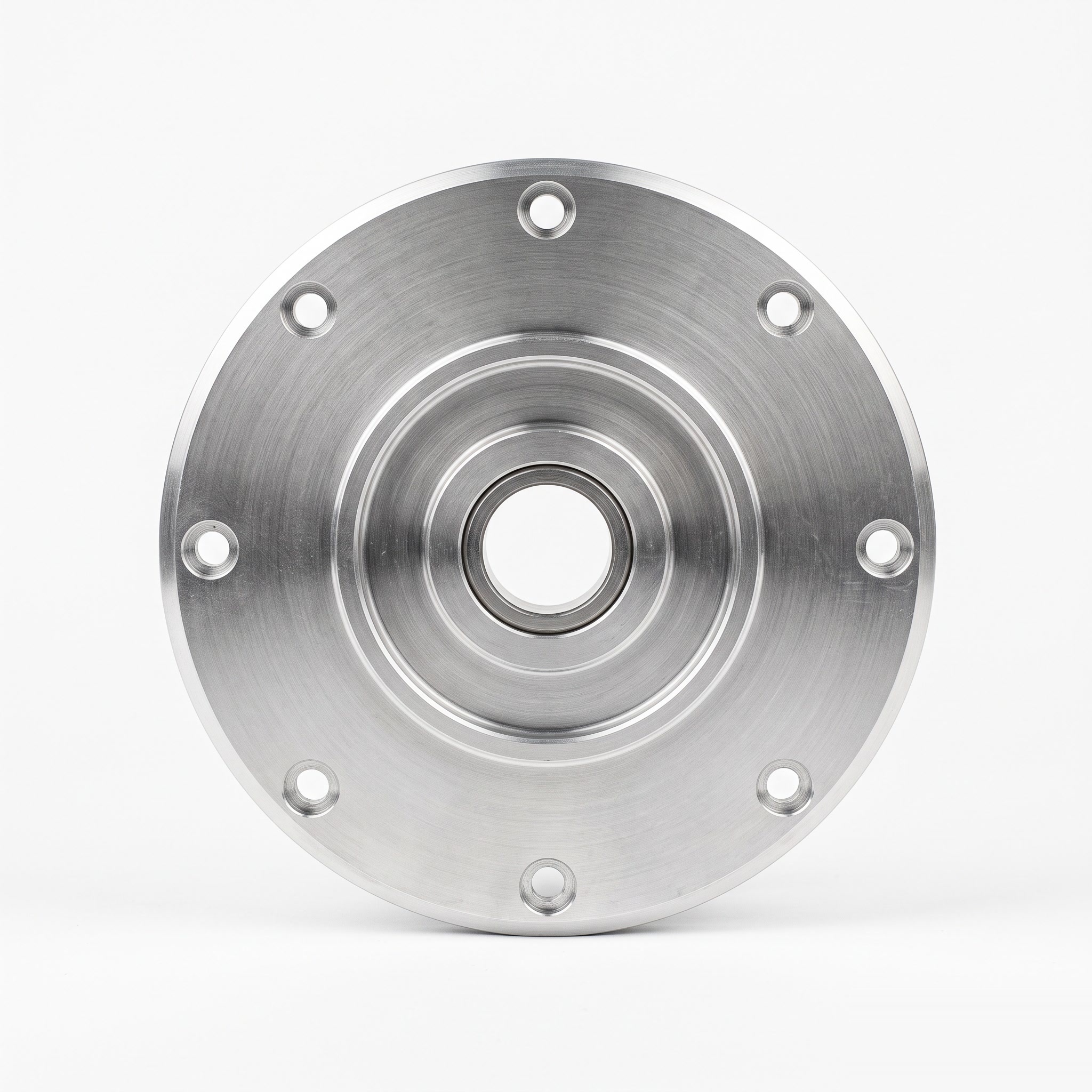
Motor Cover Plates
Circular motor cover plates with a central bore, stepped faces and perimeter fixing holes for drawing-defined motor housing interfaces.
View Details