
Circuit Board Cover Plates
Product ID: 10516
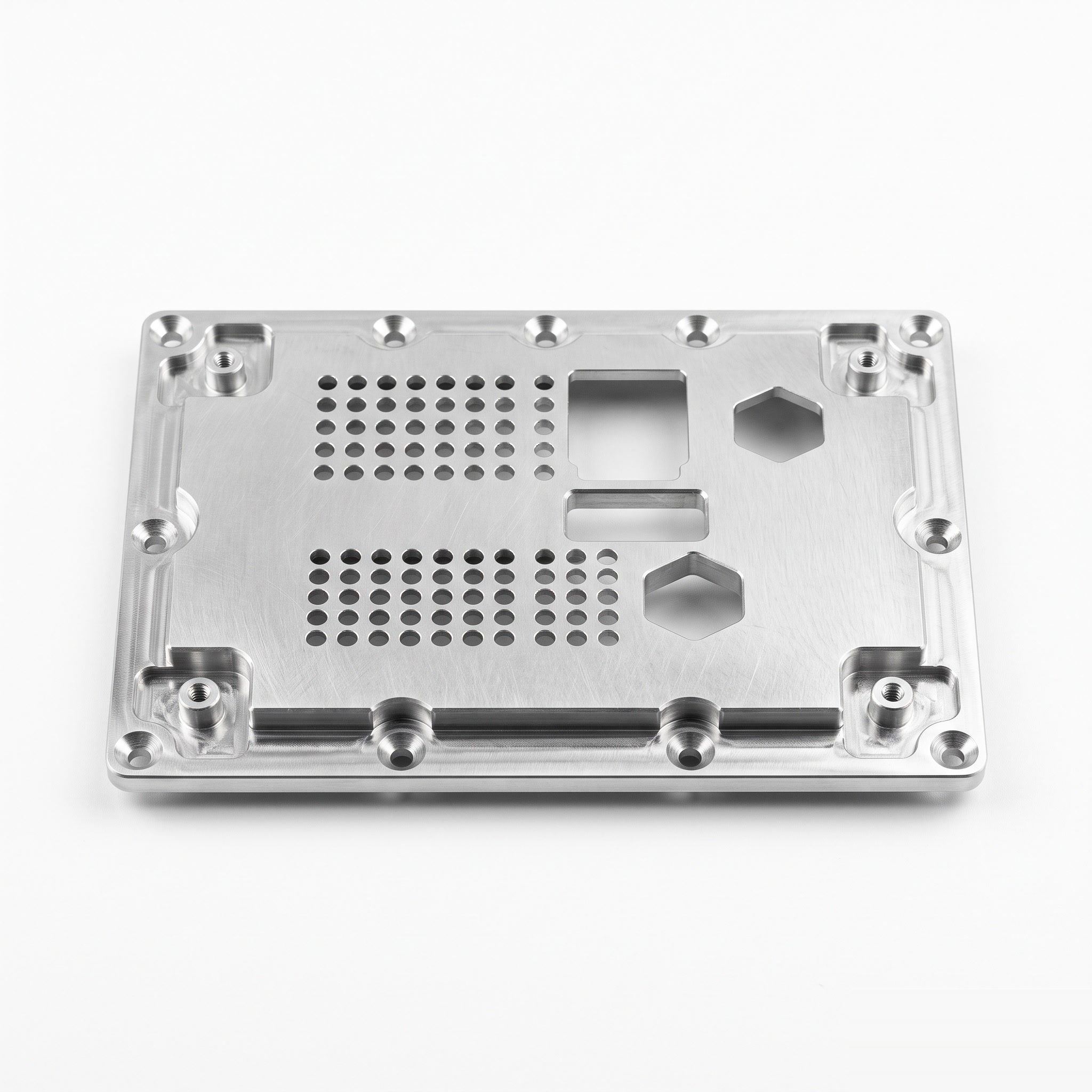
Circuit board cover plates with machined pockets, opening arrays and perimeter fixing features for customer-designed electronic assemblies.
Product Description
The plate provides a mechanical cover around the circuit-board installation area. Pockets create clearance for components, while openings provide access or other functions specified by the equipment layout. Standoff height and cover clearance must be coordinated with the tallest components and required electrical clearances. If thermal contact or electromagnetic shielding is required, contact zones and the associated materials are defined by the complete equipment design. Application examples, subject to assembly design: a control-board mechanical cover or an electronics-module interface plate. A conductive cover is not automatically an effective shield or heat spreader. A thermal path requires defined component or interface-material contact, while shielding depends on electrical continuity through the enclosure joints. Neither function should reduce the required clearance above the PCB components.
Product Features
Pockets accommodate the specified component envelope. Opening pattern follows the board and connector layout. Perimeter fixing features establish cover attachment. Controlled edge condition near boards, cables and connectors. Engineering focus: component clearance, thermal interfaces and grounding contact zones specified separately.
Technical Specifications
Indicative custom specification for RFQ; final drawing and quotation govern. Materials: 6061-T6 aluminium plate; 304 stainless alternative with separately reviewed grounding and thermal interfaces. Tolerances: General metal sizes ISO 2768-1-m; proposed pocket depths +/-0.05 mm, opening/hole position 0.05 mm and seating-face flatness 0.05 mm. Surface treatment / roughness: Clear/black anodizing 10-15 um on aluminium or stainless passivation. Ground/thermal contact zones masked or finished to the assembly drawing. Indicative size range: Length 50-250 mm; width 30-180 mm; thickness 2-15 mm; pocket depths/opening arrays coordinated with component clearance. Proposed process: Plate cutting / CNC face/pocket milling / opening drilling/milling / tapping / deburring / selected finish / layout inspection. MOQ: Reference lot 50 pcs per part number; final MOQ per quotation. Target lead time: Target 2-3 weeks (10-15 working days) after drawing/material/order approval; final quotation governs. Reference standards: ASTM B209/B209M; ASTM A240/A240M; ISO 1101:2017; ISO 21920-1:2021; ISO 7599:2018; ASTM A967/A967M; apply only to the selected material/process and scope. Note: A metal/anodized cover does not itself establish EMC shielding, dielectric safety or thermal performance. Size-range limits are not all combinable. Surface/heat treatments are project-managed through qualified partners where required.
Related products
More from Low- & Medium-Voltage Electrical Parts
Cable Clamping Plates
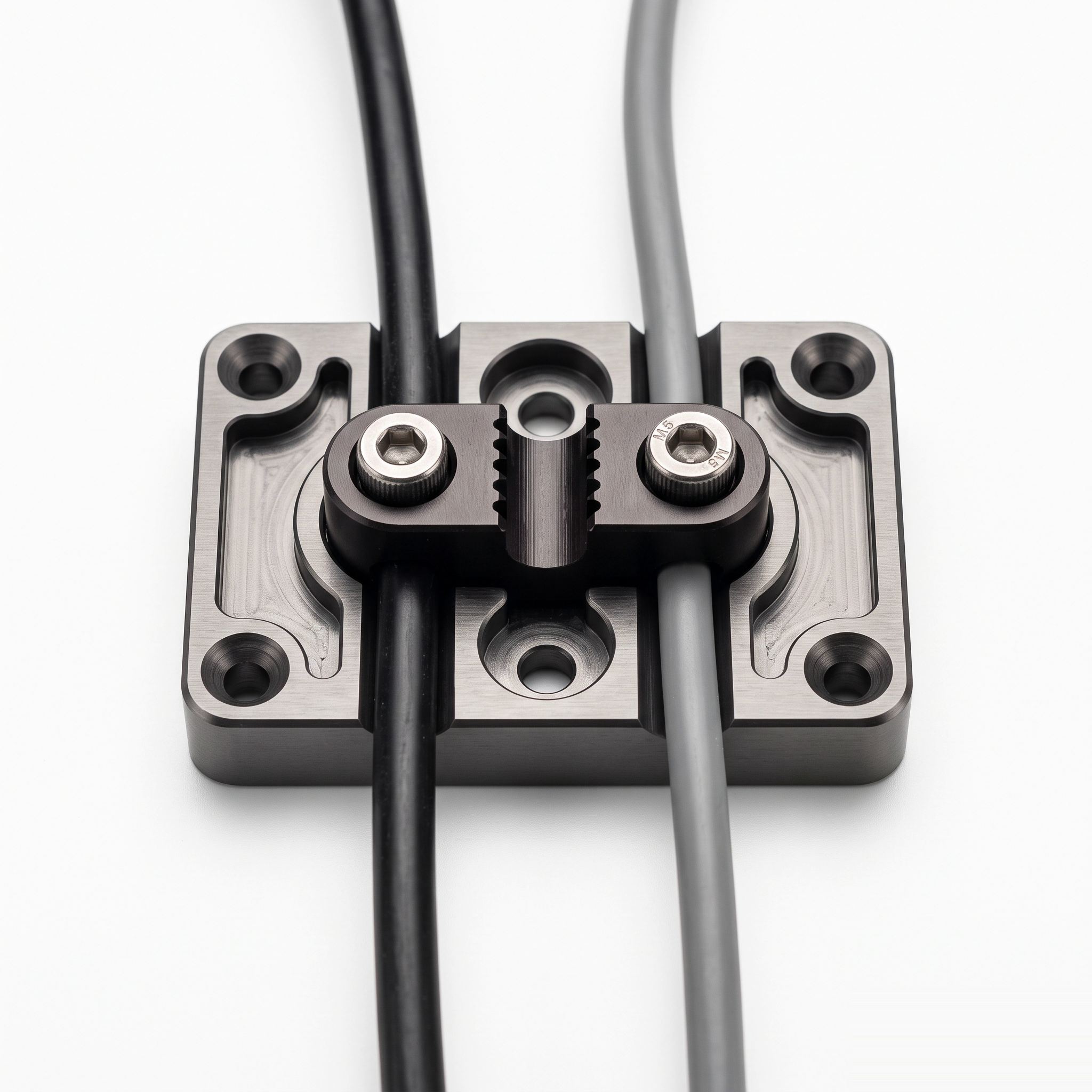
Cable clamping plates with routing channels and a screw-fastened retainer for customer-defined cable positioning and restraint.
View Details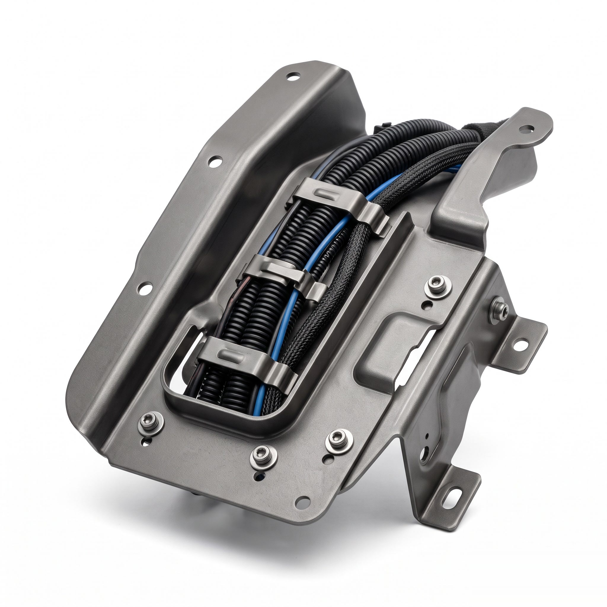
Wire Harness Protection Plates
Formed wire harness protection plates with clip locations and mounting features for organized routing within customer equipment.
View Details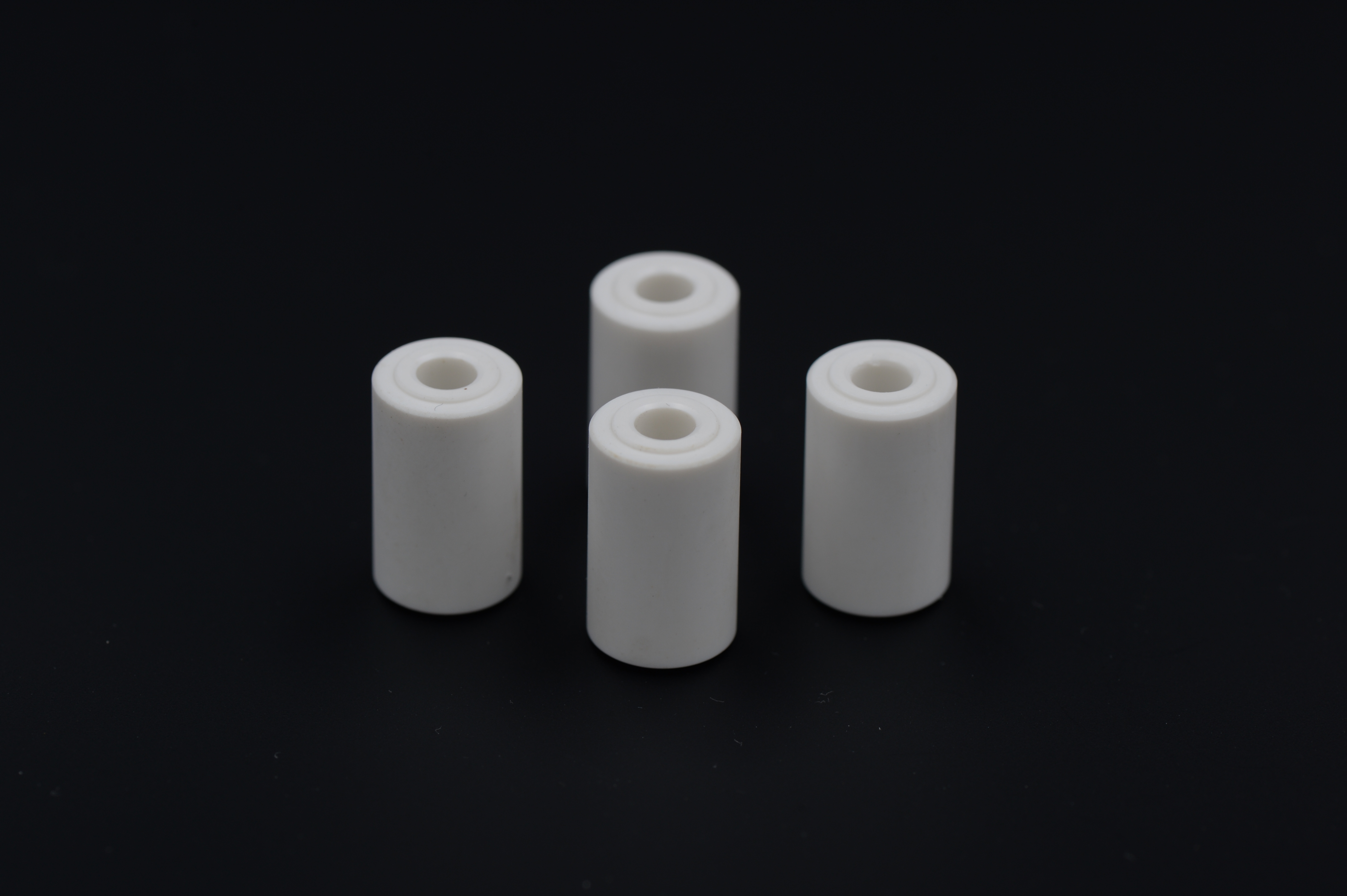
Non-Metal Spacer Sleeves
Non-metal spacer sleeves with a central bore and flat end faces for drawing-defined separation and positioning between components.
View Details